Arm Analyser
Arm_analyser
An arm analyser is a robotic arm with a proper trajectory fed with clock input and a 3D viewer using Simulink. To do this task, a trajectory planner and a mechanical model, which deals with constraints, i.e. collisions among the arm joints and objects, is used. Also, a 3D viewer, called Simulink 3D, is used to visualize the motion of the arm. The simulation of a custom robotic arm was done to gain experience with some nice features of MATLAB and Simulink for robot programming.
What is a 2 DOF manipulator 
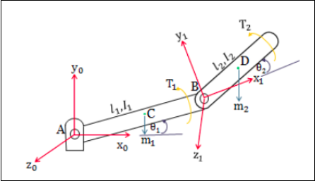
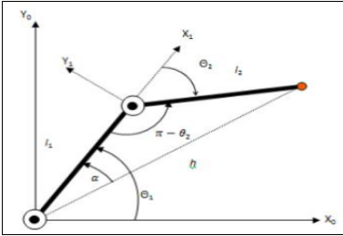
The 2-DOF robot manipulator is a mechanical system that uses several computer-controller serial chains to support a single platform or end-effector. The solutions to the kinematics problem of any robot manipulators have two types -
- Forward kinematic
- Inverse kinematics.
In forward kinematics, the end-effector position and orientation are determined from the given set of joint angles whereas, in inverse kinematics, it operates just the opposite of forward.
 |
 |
 |
Analysing the Mechanical Model
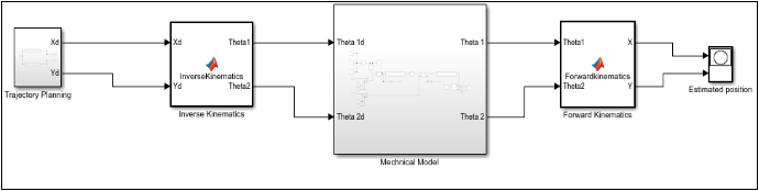
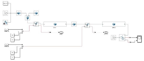
It has five main modules to handle the motion of the robotic arm. These are -
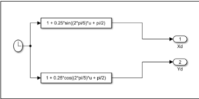
- Trajectory model - So the trajectory model contains the trajectory of our robotic arm. It takes the input from the clock and using the sin and cos function it defines the x and y path for our robotic simulation.
- Inverse Kinematics - It contains the matrices and MatLab function which takes the input as Xd and Yd from the trajectory model and feeds it to the inverse function which then calculates the theta and the required metrics and feed it to the Mechanical model of our robotic arm.
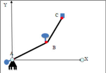
- Mechanical Model - It contains the mechanical model of our robotic arm, from the arm, leg to each joint and support in the robot. Simulink provides very handy tools such as joints, sensors, links, functions, and constant support to manage all kinds of motions.
- Forward Kinematics - Similar to inverse it also contains all the matrices and functions which take the input as theta from the mechanical model and the output as a calculated X and Y to move the arm.
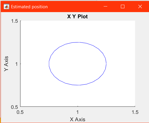
- Estimated position - It plots the graph in which the arm is moving. As initially, we took some sin and cos function for the trajectory so now it will plot the actual and expected path of the robotic arm.
Simulink Diagrams 
 |
 |
Trajectory simulation
 |
 |
 |
How to build
For building this simalation you need to open the RR.slx file in your MatLab there you will the whole mechanical model from trajectory to estimated model. You can access each block by opening it :)
Tech Stack 
- MATLAB
- Guide
- Simulink
Todo
- More support to GUI to handle all kind of motions